What is Aruba RAP?
Extend the same corporate user experience to small branch and remote sites with a solution that’s easy to deploy and manage. Aruba remote access points come preconfigured, so employees simply plug in to any existing Internet connection and they’re ready to go.
Businesses cannot afford to shut down in response to man-made incidents, natural disasters, or pandemics, so contingency planning is essential to ensure business continuity. Aruba’s Remote Access Solution helps IT departments address the daunting task of supporting a workforce that’s highly mobile and requires access to the same resources as corporate users. By providing a versatile remote networking solution, IT can securely extend the corporate enterprise network at lower cost and massive scale to easily overcome the complexity that makes traditional remote networking options poorly suited for wide-scale business continuity applications. On top of that, multiple failover options ensure that remote sites remain active in case of primary service disruption. Using the same security as Mobility Controllers in larger branches, the versatile Remote Access Points (RAPs) create a secure SSL/IPSec VPN connection back to an Aruba Mobility Controller over any wide-area transport, including 4G cellular, residential DSL, and cable networks with plug-and-play simplicity.
How to install it in your home?
RAP-3 Overview
Figure 1 Rear View (RAP-3WN Shown)
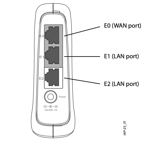
- RAP-3WNP has an additional LED called PSE.
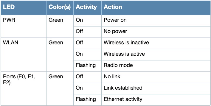
- PWR: When lit, the RAP-3 is powered on
- E0:Indicates activity and/or status on this port.
- E1: Indicates activity and/or status on this port
- E2: Indicates activity and/or status on this port
- WLAN: Indicates wireless status and activity
- PSE (RAP-3WNP only): Indicated the PSE status on the RAP-3WNP
RAP 303HR
Figure 2 303H Series (bottom)
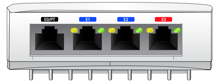
The E0/PT port, located at the back of the access point is 10/100/1000Base-T, auto-sensing, MDI/MDX wired-network uplink connectivity RJ45 port. It supports IEEE 802.3af/802.3at PoE as a standard Powered Device (PD) from Power Sourcing Equipment (PSE), such as a midspan injector, or a network infrastructure that supports PoE. The E1-E3 ports, located at the bottom of the access point are 10/100/1000Base-T auto-sensing, MDI/MDX wirednetwork downlink connectivity RJ45 ports. These ports are used to provide secure network connectivity to wired devices when physically linked using an Ethernet cable. Refer to Figure 5 for port pin-out information. Additionally, the E3 port supports PoE-out functionality, and is capable of supplying up to 15.4W to PSE when the access point is operating in 802.3at PoE mode, or powered by a DC source.
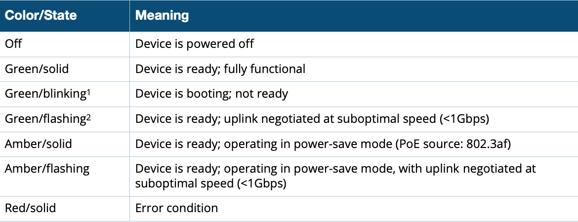
- blinking: 1s on/1s off
- flashing: on/off repeated in less than 1s
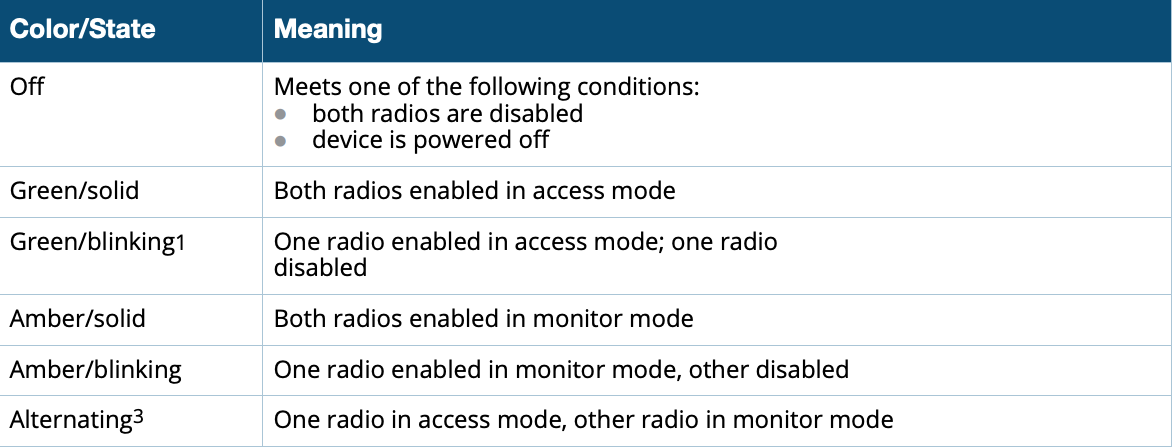
Radio Status
The Radio Status LED indicates the operating mode of the access point’s radios. See Table 2.
Table 2 Radio Status LED